The problem of separating a signal from a large noise background has been present ever since Marconi started the radio ball rolling. Over the years several methods have been found to gain improvement in reception in the presence of noise. But the problem is still with us because, in essence, noise is a signal -- a signal that has zero redundancy, to borrow a little information theory language. When a signal is said to have zero redundancy it simply means that nothing is repeated -- nothing is ever said twice and no following statement depends in any way on a previous statement. So noise, if thought of as a signal, becomes a pretty hard thing to separate from the real signal that makes sense to our ears.
There are really just two basic methods by which separation of signal from noise may be attained. These are
Noise reduction systems usually have performance which is somewhat proportional to the number of tubes. For instance, quite complex predicted wave data handling systems are able to work many dB below a white noise background and come up with almost errorless copy. But by using more bandwidth than is really necessary to contain the intelligence signal, very good noise reduction can be obtained with not too many tubes. A 24 Kc FM circuit handling 3 Kc audio is an example of a system which has excellent performance in the presence of noise, provided the intelligence signal is far enough above the threshold to control the detector.
Let us examine now in more detail the two basic noise reduction methods. In the first method, we look at the composite signal and decide on the basis of amplitude whether or not noise is present. This is the most commonly used method. A practical example of such a procedure is the double diode limiter which is adjusted to clip noise which is higher in amplitude than is the signal. In another circuit, the series limiter, the presence of a noise amplitude larger than the desired signal actually causes a series diode to open, resulting in no output for the duration of the noise pulse. In both of the foregoing circuits, however, it is notable that the improvement in signal-to-noise ratio becomes less as the amplitude of the noise approaches that of the signal. Also, if the noise lasts long enough in pulse duration, a substantial portion of the desired intelligence is lost, which equivalently reduces the effectiveness of the amplitude sensitive noise limiter.
The second method involves frequency discrimination. It depends on the fact that for noise to be especially troublesome, it must occupy a larger bandwidth than does the intelligent signal. In the simple FM talk circuit mentioned before, part of the noise reduction is secured by a limiter, and part by the frequency sensitive detector which ignores the weak noise getting through the limiter, provided a coherent signal is present with sufficient amplitude to "capture" the detector. In noise cancelling squelch systems, the wide band noise is compared to the narrow band signal to tell the squelch whether an intelligent signal is present or not. Or, it is possible to use a separate receiver tuned to a clear channel to listen for noise and to turn off the main receiver if noise occurs. This latter scheme depends on a reasonably equal noise amplitude at both frequencies and will be discussed in more detail later on.
Generally speaking then, it is a lot easier to secure good noise reduction performance when a wide band channel is used than when a narrow channel is employed which makes efficient use of spectrum space.
Another way of looking at this conclusion is to see what happens when a wide band noise impulse is passed through a selective filter. Consider a single pulse which has a high amplitude and a very short duration. The frequency distribution of such an impulse is wide, infinitely wide if the impulse is infinitely short and has infinite amplitude. When this impulse is passed through a filter, the filter allows only a selected portion of the wide band of frequencies to pass. The narrower band of frequencies so selected represents a pulse which lasts for a longer period of time and has lower amplitude than the original pulse. Since it lasts for a longer time, it will interfere with a desired intelligent signal for a greater interval, and in the case of the series limiter, the problem of eliminating it without also elimination a substantial part of the desired signal becomes more difficult. Furthermore, comparing the action of a peak limiter upon unfiltered and filtered pulses shows that, percentagewise, a greater amount of the pulse will be eliminated when the high amplitude unfiltered pulse is clipped than will occur with the low amplitude filtered pulse.
This brings us specifically to the problem of separating noise from signal when single sideband communication is being employed. Sideband communication gains its demonstrated advantage at least in part from the narrow bandwidths employed. Unfortunately, the narrow bandwidth also unavoidably means that noise pulses are stretched over a longer period of time by the filtering action previously described. Therefore, the relatively simple clipping circuits and series type noise limiters become quite unsatisfactory when applied to the audio stages of a sideband receiver having 3 Kc selectivity or less. This incidentally is one of the reasons the noise limiter was not included in the design of the 75S-1 Receiver.
The way out of this problem of generating long duration noise pulses appears to be best handled by doing our noise silencing in a part of the receiver which is ahead of the highly selective sideband filter. For instance, in the single conversion superheterodyne, a suitable point would be the plate of the mixer preceding the filter or even in the RF stage. In a double conversion superheterodyne, the high or variable IF is a logical spot to insert noise reducing circuits providing the bandwidth at that point is at least ten times as wide as that of the low IF. Ideally, the best place for noise reduction to take place is right at the antenna terminals where the noise may be silenced before it passes through any selectivity. The design problems of a practical silencing circuit which would not degrade the performance of the receiver when used ahead of the first stage become very difficult. Gating circuits, for example, when handling a very small signal as would be present at the antenna, can generated noise by the switching action of the gate which would be even louder than the original noise. If the silencing circuit had insertion loss, the receiver's noise figure would be damaged; and, since the silencing circuit must be a non-linear device, it is possible for an adjacent signal to cross modulate the desired signal to an extent greater than normally encountered.
The choice of circuit type to be employed narrows down quite a bit when the circuit has to be used at a wide selectivity point. The reason for this is that in a well designed superheterodyne, the signal level will be less than 100 microvolts following the first mixer for a signal input that is 10 dB or more above the radio's noise level. Such a small voltage level means that the contentional limiter doesn't have sharp enough action to do appreciable clipping. The series diode arrangement commonly used in audio limiters has to be discarded also because it, too, is operated by the signal, which in this case, is too low for the circuit to handle. So the circuit choice that holds the most promise seems to be a gating circuit which is switched off for the duration of the noise pulse.
The gating idea is not new. In the late 1930's, Charles Lamb of the American Radio Relay League headquarters staff popularized an IF noise silencer which used the 6L7 tube as a series gate at the IF frequency.
More recently, Collins has undertaken a development program to produce a reasonably simple noise reduction device to be used with the 75A-4, 75S-1, and KWM-1 Receivers for both fixed station and mobile use.
The following operational requirements were kept in mind:
Basically, all the above forms of noise interference are impulsive functions with repetition rates than can extend up to 100 KC in the case of the strokes in a thunderstorm.
As mentioned previously, the approach used was the series gate. But, unlike Lamb's IF silencer which depended on the amplitude of noises to trigger the gate, the new device listens in a channel separate from the communication band, and triggers the series gate whenever noise appears in the noise channel. Since the circuit actually turns off the signal path when noise occurs, the name "noise blanker" has been applied. The operation of this blanker is fundamentally based on the second method previously described where the frequency distribution of the noise causes blanker operation.
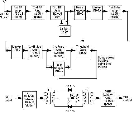
Circuit-wise, the noise blanker divides up into some fairly simple blocks. First, there is an RF amplifier used to get gain on the noise channel frequency, followed by an envelope detector, of the conventional diode type. Then, a pulse shaping amplifier handles the output of the detector to produce a gating pulse which controls the last stage, a balanced gate employing diodes which opens up the signal path whenever the pulse amplifier furnishes an output voltage. The balanced gate is inserted in the variable IF of a double superheterodyne where the selectivity is in the order of 100 KC or wider.
Let us now examine these circuits in somewhat closer detail: The RF amplifier was chosen to amplify approximately a one megacycle bandwidth at a center frequency of 40 megacycles. Since amplitude modulated signals would look like noise, it is impossible to place the noise channel further down in the high frequency range where propagation conditions are much better. If 10 megacycles were used with a 1 megacycle bandwidth, for instance, the blanker would be making false gating pulses almost all the time. In the United States, the 40 mc frequency is somewhat protected to avoid interference at the IF frequency of television receivers. The services that do operate there use frequency modulation which has little amplitude variation. The 40 MC choice has proved to be very good. About 70 dB of gain is secured in the RF amplifier, and limiting is provided so that the output amplitude can't exceed a few volts, regardless of how loud the input noise becomes.
The detector following the RF amplifier is just a half wave rectifier charging up an RC diode load. The output waveform exhibits the normal RC decay, time constant.
The pulse amplifier following the detector is both an amplifier and a limiter. The sawtooth wave out of the detector is amplified and clipped so as to produce a rectangular output pulse whose length is proportional to the amplitude of the noise pulse. This proportionality is needed for efficient blanding. If there is a small noise pulse at the input of the communication receiver, the length of the disturbance will be short in the variable IF, and it will be necessary to bland noise for only a short length of time. Blanking for a longer time than necessary just throws away more of the intelligent signal that is being copied. A large input noise impulse will make a long pulse in the variable IF which is effectively blanked by the longer blanking pulse determined by proportionality. The maximum length of blanking pulse has been made about 30 microseconds, a value which gives good results with an IF bandwidth of 100 KC.
The gating circuit resembles in many ways a double diode balanced modulator. It is operated push-pull for IF signal and single-ended for the gating pulse. With resistive and capacitive balancing controls, it becomes possible to balance the gate so that no harmonic components of the blanking pulse appear in the output. A similar circuit is used in nearly every broadcast audio compression amplifier except that the noise blanker gate action is either on or off while the compression amplifier has a smooth variation of gain.
Incorporation of a noise blanker unit into an existing sideband receiving system is not difficult. The basic requirement is that the blanking gate be inserted at a point of wide selectivity, a requirement which is met by using the high IF of double superheterodyne receivers. The antenna used for noise pickup should be as good at 40 MC as logical compromising will allow. In mobile work an ordinary 55 inch broadcast whip has been found to be satisfactory even with the high surge impedance coaxial line normally supplied with it. On the other hand, attempts to use an antenna sharply resonant at the communication channel frequency as a signal pickup for the noise blanker are prone to failure. Examples of these would be a 3.9 MC loaded mobile vertical or a three element 14 MC beam antenna. The 40 MC performance of such antennas becomes very low, rendering little noise blanker performance.
One of the prime requirements of this kind of noise blanking circuit is that it has to be faster than the receiver to which it is applied. That is, the gate must get open before the noise pulse in the communications receiver gets to it. This requirement is met by making the RF bandwidth in the noise blanker larger than the bandwidth of the communications receiver. In addition, the speed of the RF amplifier has to be preserved in the detector and pulse amplifier circuits. Practical values for the cutoff pulse driving the IF gate are 0.25 microseconds to reach an amplitude of 5 volts, and 1 microsecond to reach full amplitude. This order of performance is necessary to secure good blanking action.
Superficially, it would seem that the noise blanker circuits which have been described would be a perfect solution to impulse noise after all, the communication receiver is turned off for the duration of every noise pulse up to quite high repetition rates. But, if there is a signal being interrupted by this gating action, then sidebands spaced at the gating frequency are placed around the signal, and unfortunately these sidebands sum up to sound exactly like the noise that we are trying to eliminate. This effect is not noticeable on the signal which is actually being listened to because the noise sidebands are much weaker than the desired signal. If, though, there is a strong carrier in the passband of the high or variable IF which is a few kilocycles to the side of a weak signal, but sill outside the fixed IF passband, then the sidebands of the strong carrier produced by noise gating can cause interference to the weak signal. This effect can be ban enough under adverse conditions to actually degrade the signal-to-noise ratio when the blanker is turned on. It is an effect which seems to be inherent to any gating type system.
One premise upon which the noise blanker was originally based was that a noise which is heard, for instance, at 7 megacycles will also be present at 40 MC. If this coincidence is not true, the blanker will simply not operate. Field strength measurements on a popular make of automobile early in the development program indicated an actual peak in noise field at a frequency of 40 MC. Apparently, the assumption has held quite will because listening tests have demonstrated that for traffic noises in mobile reception, the coincidence is quite good.
The actual operation of the blanker can be startling. A tape recording was obtained while listening to an amateur station in Greenland on 21 MC. Ignition pulses were accentuated by wrapping an insulated wire around both the high tension spark lead of an automobile and the receiving antenna. The blanker brought the signal from an absolutely unreadable condition to a nearly noiseless background. Performance in heavy traffic is especially gratifying to the mobile operator accustomed to sideband operation under such conditions.